4. Connecting the device to a computer
This section provides instruction on how to connect the display to a computer.
4.1 Required Components
280 Instrument Display.
Power Cable: This cable integrates AC Power Circuit for supplying power to the Instrument Display.
Communication Cable: DB9 Connector for data communication.
PCAN Adapter.
Computer or Laptop.
4.2 Setting Up Connections
Plug the AC power adapter into a suitable power source. Ensure the DB9 connector is accessible for the next step.
Attach the PCAN Adapter.
Connect the DB9 end of the PCAN Adapter to the DB9 connector on the Instrument Display cable.
Plug the USB end of the PCAN Adapter into your laptop.
Verify Power and Communication.
Confirm that the Instrument Display powers on. If the PCAN adapter is not recognised by the computer you may need to install PCAN drivers.
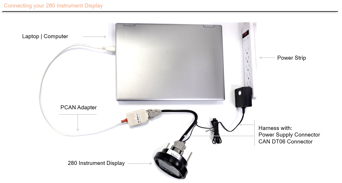
Figure 8
4.3 Configurator Tool
The Configurator Tool is ideal for quick and easy device setup to automatically populate screens with engine monitoring data through preset options and layouts. It does not need complex coding or additional resources and can also be used to quickly validate concepts.
- The Configuration Tool can configure and reflash the device. This can overwrite the existing software so ensure that you have created a backup or have the files neccesary for restoring the device before continuing.
- The 280 must be turned on when connected to the PC to be configured with the tool.
- Configuring the 280 means that its features like screens, tell tales, inputs, etc… can be customized by the user through the Config Tool:
- Settings: Model, Communication, Date & time, Wake-up & Sleep, Units, Odometer and Service Interval.
- Inputs: Digital, Resistance, Voltage and Frequency.
- Outputs: The 280 Instrument Display Base Model has one configurable output,the 280b Instrument Display Premium Model has four configurable outputs.
- Tell Tales: Configure up to five warning lights.
- Additional features are available.
- Configuration should be performed using CAN or Bluetooth communication protocols.
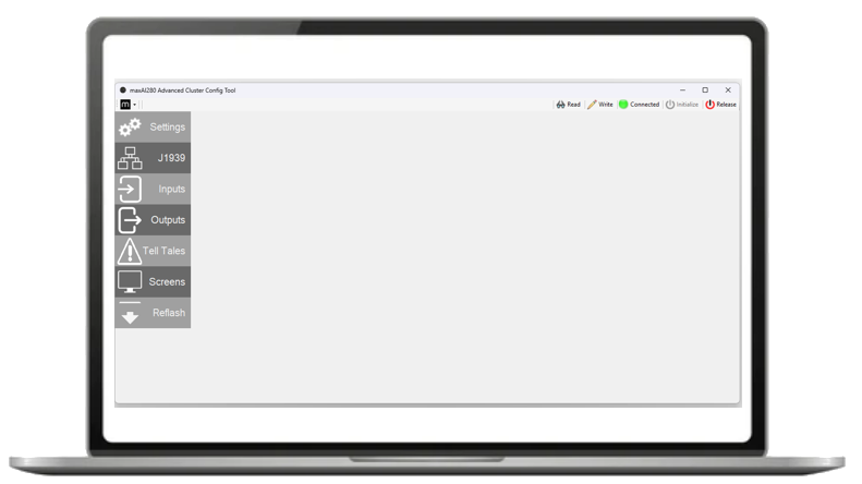
Figure 9
Please contact our Sales Department for more information and obtain the Setup Installation file.
4.3.1 Communicating with the 280 Instrument Display
Connect the Unit as described in section 4.2 Setting Up Connections.
Open the Config Tool Software. The software should be displaying the screen as described in the previous section.
At the top of the software interface, you will see buttons. Locate the one labeled Initialize and click it. Please see Figure 10 for more references.
After clicking Initialize, the software will display one of two outcomes:
If the device successfully connects the Connection Icon will change to Connected and green.
- The Read and Write buttons will now be active
- Clicking Read will retrieve all settings from the unit and load them into the tool.
- Clicking Write will apply all parameters or changes made in the configuration tool to the unit.
- The next section will provide more details about the Write button.
If the initialize sequence failed the tool will show an error message error
- Buttons Read and Write will remain as inactive.
- Retry the steps for connecting the device and try again, if the device still fails to connect please contact your established maximatecc Sales agent or Field Application Engineer for assistance.

Figure 10
4.3.2 Example project - Configuring information screens
One of the key features that the Config Tool has is the ability to design the CAN signals and the screens that will be displayed over the 280 Instrument Display. This section provides the user options to configure up to five screens. Each preset screen includes layouts designed to display commonly required operator data as values or graphs, including parameters such as engine speed, fuel level, brakes, and more. The below example configures two screens for the display.
After the Configurator Tool software has successfully initialized and the device is connected you can set the parameters for each screen.
Make sure the 280 Instrument Display is On, meaning that you can be able to see the Main Screen.
Open the Config Tool Software. The software should be displaying the screen as described in the 4.3 Config Tool section.
At the top of the software, you will see several buttons; one of them is called Initialize. Please click that button. Please see the Figure 10 for more reference.
Make sure that the icon called Not Connected change to Connected with a green indicator.
Screen 1
The Enable option must be checked.
From the Layout combo box, select Single Digital option.
From the SPN combo box select the value 190, which refers to the Engine Speed.
Go to the St L section and from the combo box select HH:MM AM PM.
Go to the St R section and from the combo box select PRND.
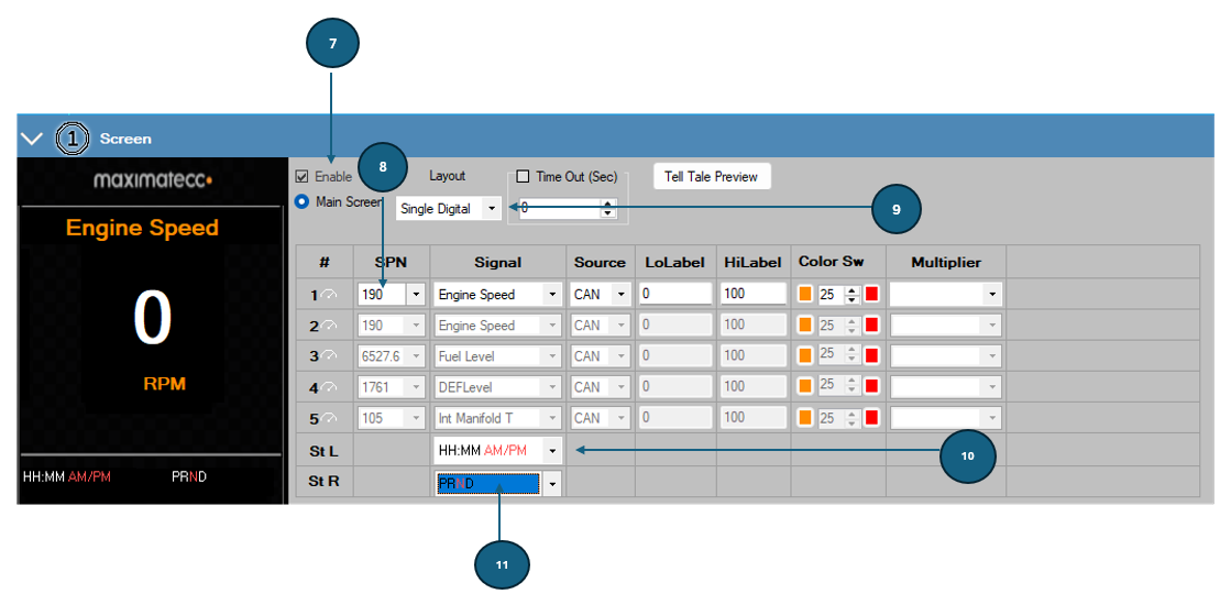
Figure 11
Screen 2
Select the Screens tab and pick the option called 2 Screen.
The Enable option must be checked.
From the Layout combo box, select Two Digital.
From the SPN combo box select the first [1] J1939 parameter, 65276, which refers to the Fuel Level. For the second value[2], select SPN 84, which refers to the Vehicle Speed.
Go to the St L section and from the combo box select HH:MM AM PM.
Go to the St R section and from the combo box select XXXXXX MI.
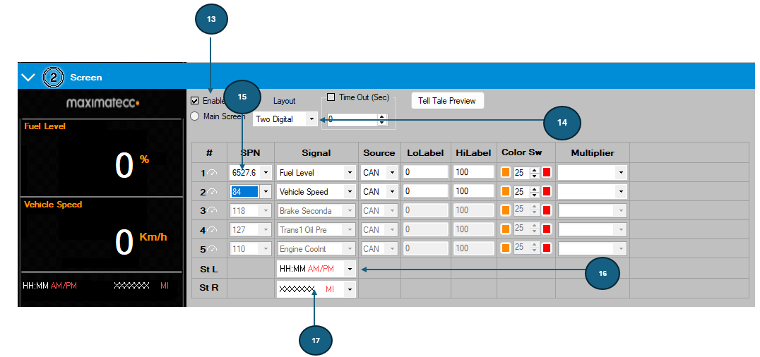
Figure 12
Click on the Write button. This step will send the changes to the unit.
A message box indicating the progress of the writing will pop up.
Once the write process is finished, the display will show the first screen with the Engine Speed parameter.
Press the Right Arrow on the 280 Instrument Display to load the second screen with the Fuel Level & the Vehicle Speed parameters.
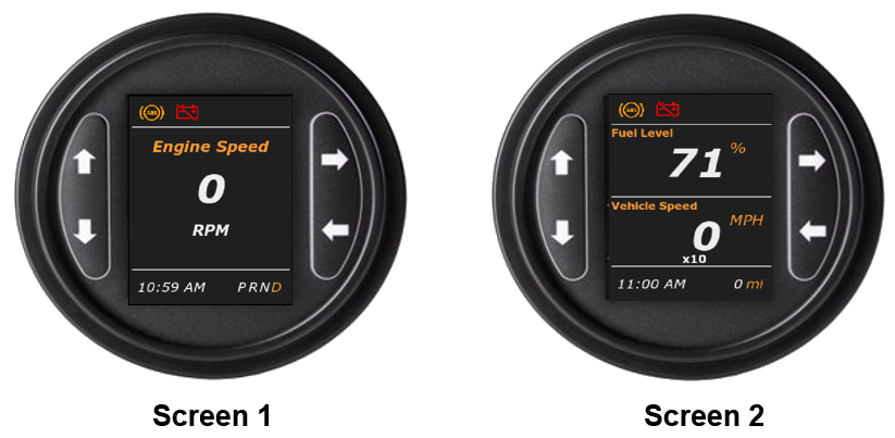
Figure 13
The configurator tool can be used to create up to five screens of information each showing unique sets of vehicle information.