3. Installation Instructions
3.1 Package Content
The 280 Instrument Display is available in 2 configurations, Basic and Premium. Both models feature the main display unit, integrated mounting hardware for secure installation. The unit is shipped with a protective cover over the display to ensure durability during transport and can be left in place to protect the unit during installation.
3.1.1 Package Contents
The package will contain your chosen display, either:
ID |
Part Number |
Quantity |
Description |
|---|---|---|---|
1 |
M-125549 |
1 |
280 Instrument Display Base |
2 |
56356-00 |
2 |
Washer |
3 |
7228 |
2 |
Nut |
4 |
71217-00 |
1 |
Bracket |
Or
ID |
Part Number |
Quantity |
Description |
|---|---|---|---|
1 |
M-125587 |
1 |
280 Instrument Display Premium |
2 |
56356-00 |
2 |
Washer |
3 |
7228 |
2 |
Nut |
4 |
71217-00 |
1 |
Bracket |
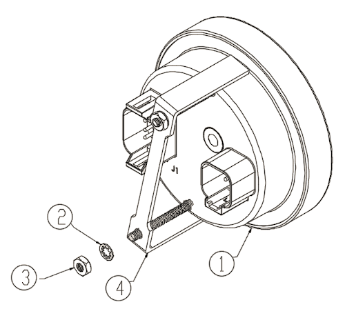
Figure 2
3.2 Additional Hardware
Development kits, which include a unit and all necessary cables, are available directly from maximatecc. Additional cables are also available. Please contact our Sales department.
3.3 Mounting
The recommended panel cut-out size for flush mounting is 87.72mm (3.375”).
Insert the instrument into the panel and secure the brackets over the mounting points using the supplied washer and nuts.
Tighten the nuts [5.0 to 6.0 in-lb (0.565 to 0.678 Nm)] to secure the instrument.
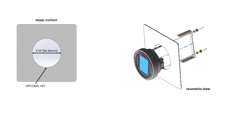
Figure 5
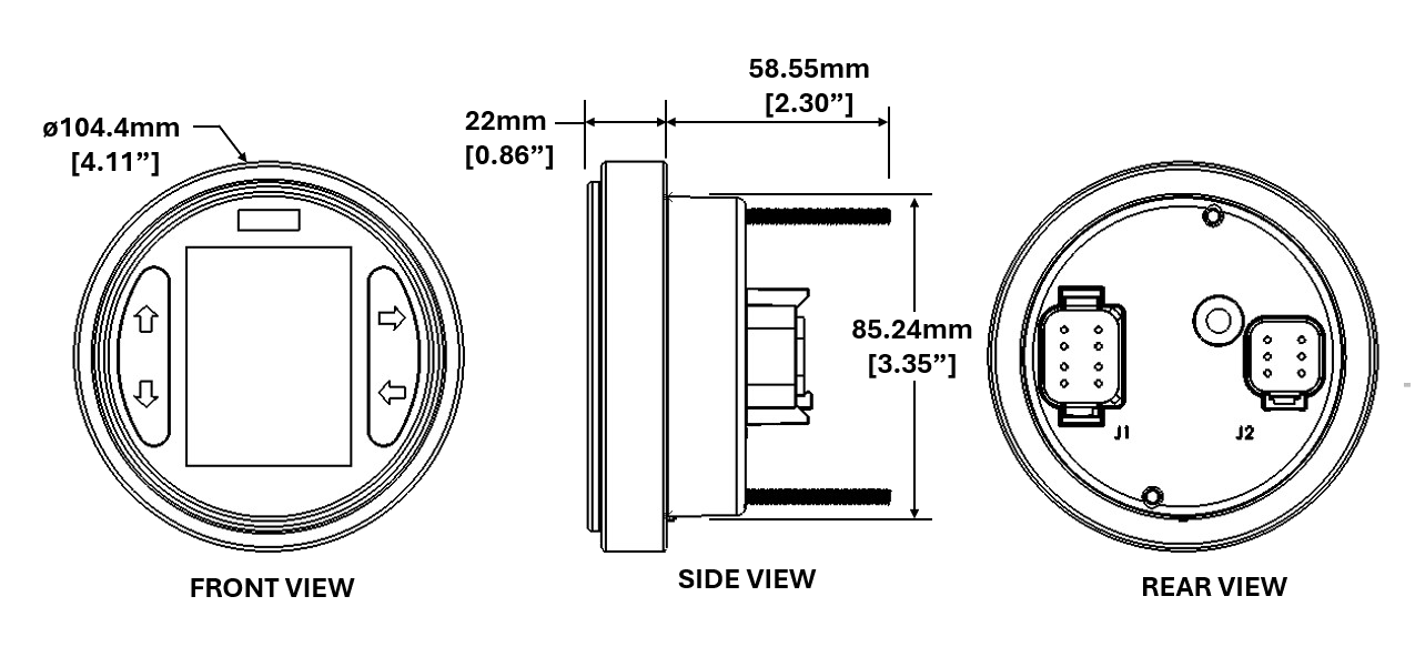
Figure 6
3.4 Wiring
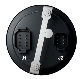
Figure 7
Connector J1 Pinout
Pin Number |
Description |
State |
|---|---|---|
J1.1 |
Power |
Battery+ |
J1.2 |
Power |
Key On |
J1.3 |
CAN |
CAN Low |
J1.4 |
CAN |
CAN High |
J1.5 |
Config. Input |
Voltage/digital/resistance/freq. |
J1.6 |
Config. Input |
Voltage/digital/resistance/freq. |
J1.7 |
Digital Output |
Low/high side driver |
J1.8 |
Power |
Ground |
Per the SAE-J1939 specification, the instrument does not include a bus termination resistor.
Connector J2 Pinout (280b Instrument Display)
Pin Number |
Description |
State |
|---|---|---|
J2.1 |
Digital output |
Low/high side driver |
J2.2 |
Digital output |
Low/high side driver |
J2.3 |
Config. input |
Voltage/digital/resistance/freq. |
J2.4 |
Config. input |
Voltage/digital/resistance/freq. |
J2.5 |
Config. input |
Voltage/digital/resistance/freq. |
J2.6 |
Digital Output |
Low/high side driver |
NOTE: Of the five available inputs, only one can be dedicated to digital input. This means the device can have one digital input with up to four analog inputs or no digital inputs with up to five analog inputs.