Knowledge Center - CAN bus FAQs
Below you'll find frequently asked questions surrounding our products and their operating systems.
To learn more about our software, please visit the Knowledge Center - Software page by clicking the button below.
Understanding SAE J1939 data bus (CAN bus)
a) While this information applies to many types of CAN bus systems, the maxAI products typically operate via the SAE J1939 CAN bus and CANopen protocols.
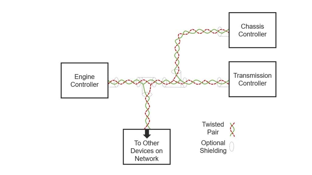
b) The CAN bus is like an information superhighway in the vehicle. A CAN bus allows various controllers, such as the engine, transmission or chassis controller, to communicate with each other and any other connected components.
c) Most modern diesel engines are controlled by an engine control module (ECM) that uses information from various sensors to adjust operating parameters, such as fuel injection, to optimize power, increase fuel economy and lower emissions. The CAN bus enables the ECM to send and receive vast amounts of information to and from the transmission computer or any other computer connected to the CAN bus, greatly simplifying the vehicle’s electrical system.
d) The CAN bus contains most operating information about the vehicle, such as engine and vehicle speed, coolant and oil temperatures, oil and fuel pressures, as well as error codes from the various controllers.
a) The physical aspects of the CAN bus are quite simple. It’s nothing more than a pair of wires twisted together, commonly referred to as a twisted pair, running from one controller to another.
b) As engine applications become more complex, networks will have a lot of controllers, sensors and input devices that can complicate wiring. Modern CAN bus displays, like the maxAI, feature input and output (I/O) functionality in addition to CAN connectivity. The main benefit the maxAI offers with this capability is reduced wiring complexity. Devices located in close proximity could be wired directly into the maxAI display, which can reduce wire complexity and free I/O on other controllers.
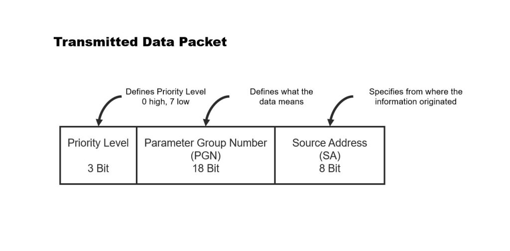
a) SAE J1939 CAN bus devices transmit data to or receive data from the bus. Data is broken down into a structured format, designated specifically by the SAE standard, containing a source address (SA), a parameter group number (PGN) and parameter data.
b) The source address is the number at the beginning of the data packet that identifies where the data was transmitted from. For example, SA 0 indicates that the data packet was transmitted from source address zero, which is the primary ECM.
c) The parameter group number is the identification label for the group of data that follows the PGN. This defines what type of information the parameter data will be (e.g., engine oil pressure values). The parameter data is a group of data bytes that contain the specific values of the particular PGN parameters (e.g., engine oil pressure).
d) A device, like the maxAI, will be programmed to operate as follows:
i) Monitor the network continuously
ii) Listen for a specific SA and PGN
iii) Identify the specific SA and PGN on the network if it is transmitting
iv) Collect data or read the message attached to the SA and PGN
v) Execute any pre-programmed functionality that is part of the maxAI configuration:
(1) Display the information (speed, RPM)
(2) Notify or warn the operator (high temperature)
(3) Control or perform Logic (if value is x, then do y)
(4) Output data to the network or other connected devices
a) The SAE specification for the J1939 CAN bus requires CAN bus termination. The J1708/1587 CAN bus does not require termination. Termination is required to reduce any electrical noise developed by the high-speed data transfer. If the termination resistors are not present, loss of CAN bus communication may occur.
b) Termination simply means installing two, 120 ohm, half-watt resistors between positive bus wire and negative bus wire at each end of the CAN bus backbone. If the installation involves connecting to an existing CAN bus, termination should already exist, and no additional termination is required. The SAE specification forbids the use of internal CAN bus termination because the CAN bus must remain intact if any device is removed. If a specific module terminated the CAN bus, and that module was removed, then the CAN bus could cease to operate.
c) The CAN bus shield must also be terminated properly. Using a wire, the shield should be connected to ground as close as possible to the battery ground. This termination connection to ground can be anywhere along the CAN bus, but it must only be connected at one point. The shield should also connect to the shield pin of all CAN bus devices, not ground.
d) Per the SAE J1939 specification, bus shielding is optional and may not be found on all systems.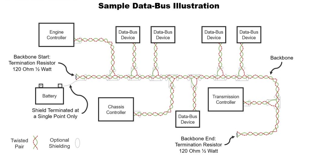
a) Fault codes are displayed according to J1939-71 error definition. Fault codes are often referred to as diagnostic trouble codes (DTC) and are a way for the operator to be alerted to system abnormalities or malfunctions.
b) The DTC itself is made up of four independent fields, including suspected parameter number (SPN), failure mode identifier (FMI), occurrence count (OC) and SPN conversion method (CM).
c) An important feature of modern CAN bus displays, like the maxAI products, is to continuously monitor the network and notify the operator when certain active DTC messages appear. Additionally, displays like the maxAI can be programmed in a way that allows the operator to navigate to dedicated screens in the display and view active faults, view inactive faults, and clear faults.
d) The priority of DTC fault codes, and how an operator is informed of them, will vary by application. It is important to note that specific DTC functionality can be programmed within the maxAI software development tools.
e) As a point of reference, review the fault code chart for a list of some common DTC codes or refer to J1939-71 for all DTC definitions.
Common Fault Codes
| Suspect Parameter Number (SPN) | Failure Mode Indicator | Signal |
|---|---|---|
| 100 | 0-31* | Engine Oil Pressure |
| 105 | 0-31* | Temperature |
| 110 | 0-31* | Engine Coolant Temperature |
| 158 | 0-31* | Keyswitch Battery Power |
| 168 | 0-31* | Battery / Power Input |
| 190 | 0-31* | Engine Speed |
| 106 | 0-31* | Engine Intake Air Pressure |
| 558 | 0-31* | Accelerator Pedal 1 Low Idle Switch |
| 651 | 0-31* | Engine Fuel Injector Cylinder 1 |
| 676 | 0-31* | Engine Glow Plug Relay |
Engine monitoring displays are designed to continually check the status and health of a vehicle or machine. They are equipped with powerful designs and an innovative range of software platforms and tools created to offer a superior user experience. Review our white paper for guidance in choosing the right engine monitoring display to fit your needs.
| Message | Parameter Group Number (PGN) | Suspect Parameter Number (SPN) | Signal |
|---|---|---|---|
| CCVS | 65265 | 84 | Wheelbase Vehicle Speed |
| EEC1 | 61444 | 190 | Engine Speed RPM |
| EEC2 | 61443 | 92 | Engine Percent Load at Current Speed |
| EF1_P1 | 65263 | 100 | Engine Oil Pressure |
| ET1 | 65262 | 110 | Engine Coolant Temperature |
| HOURS | 65253 | 247 | Engine Total Hours of Operation |
| IC1 | 65270 | 105 | Engine Intake Manifold Temperature |
| LFE1 | 65266 | 183 | Engine Fuel Rate |
| LFE1 | 65266 | 51 | Throttle Position |
| LFE1 | 65266 | 185 | Fuel Economy |
| TRF1 | 65272 | 127 | Tranmission Oil Pressure |
| TRF1 | 65272 | 177 | Tranmission Oil Temperature |
| VD | 65248 | 244 | Trip Distance |
| VEP1 | 65271 | 168 | Battery Voltage |
| LFC | 65257 | 182 | Current Fuel Consumption |
| ETC2 | 61445 | 523 | Transmission Current Gear |
| AT1T1I1 | 65110 | 1761 | DEF Level, Aftertreatment 1 SCR Catalyst Tank Level |
All fault codes originate from a source address (SA). An engine fault would originate from source address zero, from the engine control module (ECM). A transmission fault would originate from source address three, from the transmission control module (TCM).
Common Fault Codes
| Suspect Parameter Number (SPN) | Failure Mode Indicator | Signal |
|---|---|---|
| 100 | 0-31* | Engine Oil Pressure |
| 105 | 0-31* | Temperature |
| 110 | 0-31* | Engine Coolant Temperature |
| 158 | 0-31* | Keyswitch Battery Power |
| 168 | 0-31* | Battery / Power Input |
| 190 | 0-31* | Engine Speed |
| 106 | 0-31* | Engine Intake Air Pressure |
| 558 | 0-31* | Accelerator Pedal 1 Low Idle Switch |
| 651 | 0-31* | Engine Fuel Injector Cylinder 1 |
| 676 | 0-31* | Engine Glow Plug Relay |
The maxAI 430 and the maxAI 280 product line have highly configurable inputs. They can be configured using the maxAI Configurator Tool or with software using the maxAI Design Studio to the following signals:
• Frequency up to 10 kHz, compatible with typical inputs such as magnetic pickups, Hall effect sensors, alternators, and ECUs
• Analog inputs from sensors in the 0-5V range e.g., 5V to 4.5V.
• Switched digital inputs such as switch to battery or ground in 12 or 24V systems.
• Digital inputs from electronic control units.
• Analog resistance inputs from a traditional sender (e.g., 240 to 33 ohm match fuel senders). Non-linear curves are easily implemented with piecewise linear transfer function.
• Pulse width modulation input such as dimmer controls.